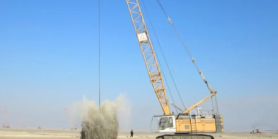
Rockhampton sits on the alluvial plains of the Fitzroy River, where the soil profile typically consists of loose river sands, silty clays, and soft estuarine deposits extending to depths of 8 to 12 meters. Groundwater levels fluctuate with the monsoon season, often sitting between 2 and 4 meters below surface. For projects on reclaimed areas or former floodplains, dynamic compaction design becomes the primary method for densifying these loose granular layers. The technique involves dropping a heavy tamper—typically 10 to 20 tonnes—from heights of 12 to 25 meters in a controlled grid pattern to reduce void ratios and improve bearing capacity. Before mobilizing equipment, we always cross-check the target depth with a MASW survey to map velocity contrasts, ensuring the tamper energy reaches the critical loose zones without over-penetrating into competent strata.
Dynamic compaction in Rockhampton's alluvial soils requires phased energy application with pore pressure dissipation waits between passes to achieve uniform densification.
Scope of work
Area-specific notes
Rockhampton's development has expanded steadily into former floodplains and low-lying areas east of the city centre since the 1960s. These reclaimed zones often contain loose hydraulic fills and soft compressible clays that are prone to differential settlement under structural loads. Without a properly designed dynamic compaction program, the risk of excessive total settlements—sometimes exceeding 100 mm—can compromise slab-on-ground foundations, road pavements, and buried utilities. The seasonal wet-dry cycle further exacerbates moisture changes in the upper soil layers, making post-construction movements unpredictable. We address this by designing a compaction grid that accounts for both the static load from the structure and the cyclic loading from seasonal groundwater fluctuations, ensuring the improved ground behaves consistently throughout the year.
Standards used
AS 1726 – Geotechnical site investigations, AS 4678 – Earth retaining structures (reference for Improvement quality control), AS/NZS 1170 – Structural design actions (dynamic loads consideration)
Linked services
Site Investigation & Soil Profiling
Boreholes, test pits, and CPT soundings to characterize the alluvial layering and locate loose zones requiring treatment.
Compaction Design & Energy Calculation
Determination of tamper weight, drop height, grid spacing, and number of passes using the Menard method, calibrated to local soil conditions.
Post-Compaction Verification Testing
CPT, plate load tests, and density cone (sand cone) testing to confirm the achieved relative density and bearing capacity meet design criteria.
Typical parameters
FAQ
How does dynamic compaction compare with vibrocompaction for Rockhampton's sandy soils?
Dynamic compaction is generally preferred for sites with a higher percentage of fines (silts and clays) or where loose layers extend deeper than 6 m. Vibrocompaction works better in clean sands with less than 10% fines. For Rockhampton's alluvial silty sands, dynamic compaction achieves greater depth of influence and is less sensitive to groundwater than vibro methods.
What is the typical cost range for a dynamic compaction design in Rockhampton?
The cost for dynamic compaction design and supervision in Rockhampton typically falls between AU$2.140 and AU$6.050, depending on the area to be treated, depth of loose layers, and number of verification tests required. This range covers the design phase, field supervision during drops, and post-compaction testing.
Can dynamic compaction be applied near existing structures or buried utilities?
A minimum setback of 10 to 15 m from existing structures is recommended to avoid vibration damage. For sites with buried utilities, we first conduct a GPR survey to locate them, then either relocate the utilities or switch to a lower-energy technique like rapid impact compaction for the buffer zone. The dynamic compaction grid is adjusted so that high-energy drops avoid these areas.